


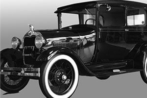
Introduced to the public in late 1927 as a "New Ford Car"
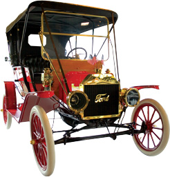
The Ford Model A could trace its roots all the way back to the establishment of the Ford Motor Company in 1903. Actually, the first car produced by the developing auto manufacturer was labeled the Model A. Henry Ford would work his way through a series of letter designations for his automotive creations before settling on the successful formula that would become the Model T. In the years that followed, as America’s roads and driveways filled with Model T’s, Henry Ford would remain reluctant to significantly tamper with his beloved car’s design.
 It was only in the face of plummeting sales by the mid 1920’s, the result of a buying public that sought the modern upgrades offered by Ford’s competitors, that Ford finally relented. In an unusual business move, Ford halted production of the Model T in May of 1927, shutting down the entire production operation for 6 months to allow for retooling and final development of the new Model A Ford.
Working under an impossible deadline, Ford managed to get the design and production requirements in place for the release of the “New Ford Car” by November of 1927. Henry’s son, Edsel Ford, had unsuccessfully tried to convince his father to abandon the Model T years earlier. Unbeknownst to his father, Edsel had been secretly working on the development of a new car and would ultimately play a significant role in the design of what would become the Ford Model A.
 Henry Ford's goal to create a "universal car" was not limited to the car's design. Aiming for a vehicle that would be reliable, easily maintained, and affordable, the Model T Ford was introduced in 1908 at a price of $850. Ford's implementation of assembly line manufacturing in 1913 would drastically reduce build time, as well as production costs. As a result, the price of the car dropped, selling as for as little as $260 in 1925.
Unlike its predecessor, the Model T, which was the result of an evolving process of design, the Model A was designed, complete, from the ground up. The Model A was truly a “New Ford Car.” Mechanical upgrades for the Model A Ford included a new 3-speed transmission, hydraulic shock absorbers, and four-wheel mechanical brakes. Other significant improvements were an electric starter, water pump, speedometer and gas gauge, and the introduction of Triplex safety glass. The styling of the Ford Model A, elegant and integrated compared to the Model T, brought Ford into the modern era with a vehicle that looked more like a car and less like a horseless carriage.
Henry Ford created a sense of hype and mystery surrounding the release of the Model A Ford, relying on the media to reach the buying public and generate interest in the “New Ford Car.” Shortly after the Ford Model A was made available to the public on December 2, 1927, orders for the new car far exceeded supply. Ford scrambled to increase production and by mid 1928, producing up to 4,000 cars per day, was still not meeting the buying public’s demand. In an effort to meet demand, Ford steadily boosted production, peaking at around 9,200 cars per day by June of 1930.
During its four-year production run, the Model A Ford would be offered in a wide variety of car and truck body styles. For 1928, Ford offered several different style passenger car bodies: Standard Phaeton, Standard Roadster, Standard Coupe, Special Coupe, Sport Coupe, Business Coupe, Tudor Sedan, Town Car, and Leatherback Fordor Sedan. Truck bodies included: Open Cab Pickup, Closed Cab Pickup, Pickup (box), “A” Panel Delivery, “AA” Panel Delivery, and Deluxe Delivery.
In 1929, Ford expanded the options for passenger car body styles by adding the Steelback Fordor, Cabriolet, Station Wagon, both Murray and Briggs versions of the Town Sedan, as well as Murray and Briggs versions of the Standard Fordor. The Standard Fordor (2 window) was also introduced. Options for truck bodies remained the same from the previous year.
For 1930, the Leatherback and Steelback Fordors, as well as the Special and Business Coupes, would be dropped from the lineup. New passenger car bodies included the Deluxe Phaeton, Deluxe Roadster, Deluxe Coupe, Deluxe Fordor (2 window) and Victoria. Truck body options included the addition of the Deluxe Delivery and Panel Delivery (drop floor), Special Delivery, Town Car Delivery, “AA” Panel Delivery and the “AA” Deluxe Delivery.
1931, the final year of Ford Model A production, would mark the most extensive offering of passenger car and truck body styles in the vehicle’s brief history. New passenger cars for 1931 were the Deluxe Tudor, Slant Window Cabriolet, Slant Window Standard Fordor, Slant Window Town Sedan, Slant Window Deluxe Fordor (Blindback) and Convertible Sedan. The Standard Fordor (2 window) and Town Car were no longer offered. For truck bodies, a Deluxe Pickup and a wide bed Pickup (box) were introduced.
Like the rest of the nation, the Ford Motor Company would endure the effects of the economic Depression that began with the stock market crash in October of 1929. Despite reducing prices for 1931, Ford continued to see a steady decline of new car sales.
Perhaps learning from his mistake of sticking with the Model T long after the public regarded it as outdated, Henry Ford had been actively working on a new design for 1932. The successful development of the new V8 Ford for 1932 would ultimately put an end to the short but successful run for “Henry’s Lady,” the Model A Ford.
What Would You Like More Information On?
Clicking on a topic will jump you to that section.
Model A Identification
Model A Vehicle Identification
Body Type Identification Charts
How to Tell a Briggs From A Murray
MAC's DISCLAIMER:
The content MAC's presents on its "Vehicle Identification & Specification" pages & in its catalogs is for information use only and is intended to be used as a guide. While MAC's makes every effort to ensure accurate content, occasionally errors may occur. MAC's does not take responsibility & will not be held liable for any automotive parts purchases, repairs or restoration decisions made as a result of information presented here or anywhere in its catalogs.
Model A Specifications
Rear Emergency Brake Specifications
Front Axle & Spindle Specifications
7-Tooth Steering Gear Specifications
2-Tooth Steering Gear Specifications
2-Tooth Steering Gear Housing Casting
Vehicle Identification

1928-29 STANDARD COUPE (45-A)

1928-29 SPECIAL COUPE (49-A)

1930-31 STD & DLX COUPE (45-B)

1928-29 BUSINESS COUPE (54-A)

1928-29 SPORT COUPE (50-A)

1930-31 SPORT COUPE (50-B)

1929 CABRIOLET (68-A)

1930-31 CABRIOLET (68-B)

1930-31 VICTORIA (190-A)

1930-31 CONVERTIBLE SEDAN (400-A)

1928-29 TUDOR SEDAN (55-A)

1930-31 TUDOR SEDAN (55-B)

1929 STEELBACK FORDOR (60-C)

1929-31 2-WINDOW FORDOR (170-A,B)
-.jpg)
1929-31 3-WINDOW FORDOR (BRIGGS)
(155-B,D/165B,D)
.jpg)
1929-31 3-WINDOW FORDOR (MURRAY)
(155-A,C/165A,C)
.jpg)
1930-31 SLANT WINDSHIELD FORDOR (160-A,B,C)

1928-29 LEATHERBACK FORDOR (60-A,B)

1928-29 STANDARD PHAETON (35-A)

1930-31 STANDARD PHAETON (35-B)

1930-31 DELUXE ROADSTER (40-B)

1928-29 STANDARD ROADSTER (40-A)

1930-31 STANDARD ROADSTER (40-B)

1930-31 DELUXE PHAETON (180-A)

1928-29 OPEN CAB PICKUP (76-A)

1930-31 OPEN CAB PICKUP (76-B)

1928-29 CLOSED CAB PICKUP (82-A)
1930-31 CLOSED CAB PICKUP (82-B)

1928-29 STATION WAGON (150-A)

1930-31 STATION WAGON (150-B)

1928-29 (60-A,B) LEATHERBACK 4 DOOR SEDAN

1929-31 (170-A,B) 2 WINDOW 4 DOOR SEDAN

1929 (60-C) STEELBACK 4 DOOR SEDAN
1931 (160-A) SLANT WINDOW 4 DOOR MURRAY SEDAN
Model A Body Style Identification Front & Side View

1928-29 Front View

1928-29 Cowl Side View

1930 Front View

1931 Front View

1930-31 Cowl Side View
Body Type ID Chart
Passenger Vehicles
(Slant Window)
(Murray)
(Briggs)
(Slant Window)
(Slant Window)
(2 Windows)
(2 Windows)
Body Type ID Chart
Commercial Vehicles
(131-1/2")
(Drop Floor)
(Drop Floor)
* Change-over from 1929 to 1930 models was in January, 1930 for passenger cars & in June, 1930 for commercial vehicles.
** If you cannot decide if your car body is a 60C or a 170A you can quickly tell by examining the front door post. If it is all steel, it is a 170A. If it has wood parts, it is a 60C.

Glass Specifications

To please the perfectionist, we offer Concours grade windows – intended for car show & points competition automobiles. These are superior quality 1/4" laminated safety glass (AS1 CAT-II). Exposed edges are beautifully polished or black edged & the original manufacturers sandblasted script (logo & date, sometimes referred to as the “bug”) is duplicated to reproduce the O.E.M. appearance (because they’re concours, tint options are not available). These details are applied with great care & meticulous craftsmanship.
Black edging refers to the process used to seal exposed glass edges & was necessary in the early years of automobile manufacturing. Early laminated safety glass often separated at the edges, allowing water & other contaminants between the panes. The solution was to seal the edges with a sealant. Advances in the laminating process rendered black edging obsolete in 1941, but MAC's craftspeople have re-discovered & are practicing this lost art for the detail oriented customer.
Wheel Specifications
Material: Steel
Diameter: 1928-29 21", 1930-31 19"
Rim: Drop center type; width, 1928-29 2-3/4", 1930-31 3"
Number of Spokes: 30, 1/4" diameter
Tire Specifications
Size: 1928-29, 4.50" x 21" 1930-31, 4.75" x 19"
Recommended Tire Pressure: 35 Lbs
Station Wagon: 5" x 21" or 19", pressure 40 lbs
Tread Width: 21" = 3.75", 19"3.90"


Excelsior
19" or 21"

Universal
19" or 21"

Bedford
19"
Front Brake Specifications
Braking Power: Front, 40%; Rear, 50%
Drum Diameter: 11" +/- .010"
Drum Width: 1-3/4"
Brake Shoe Length: 14"
Brake Shoe Width: 1-1/2"
Brake Shoe Lining Thickness: 3/16"
Brake Shoe Material: Woven wire & asbestos
Brake Rod Length: 51-7/16" thru 51-1/2"
Rear Emergency Brake Specifications
Drum Diameter: 9-5/8"
Drum Width: 1-3/4"
Brake Shoe Length: 28-3/4"
Brake Shoe Width: 1"
Brake Shoe Lining Thickness: 3/16" (original), 1/8" (ours)
Brake Shoe Material: Woven wire & asbestos
Front Axle & Spindle Specifications
Material Chrome alloy forging
Tensile Strength 125,000-145,000 PSI
Caster 5" (forward tilt)
Toe In 1/16" +/- 1/32"
Camber 1-13/16"
Spindle Bolt Diameter .8125" +/- .005"
Spindle Bolt Length 5-5/16"
Spindle Bolt to Bearing Clearance .001"-.002"
7-Tooth Steering Gear Specifications
Turning Radius: 17' (34' diameter)
Steering Gear Ratio: 1928-29, 11-1/4:1
Steering Wheel Diameter: 1928-29, 17-1/2"
Pitman Arm Length: 6-7/8" hole center to ball center
Ball End Angle to Shaft: 14°
Sector Shaft Bearing Clearance: .001"-.002"
2-Tooth Steering Gear Specifications
Turning Radius: 17' (34' diameter)
Steering Gear Ratio: 1930-31, 13:1
Steering Wheel Diameter: 1930-31, 17"
Pitman Arm Length: 6-7/8" hole center to ball center
Ball End Angle to Shaft: 14°
Sector Shaft Bearing Clearance: .001"-.002"
Except for minor machining differences, all the above housings are virtually identical mechanically
& all new parts furnished will fit each one.
Ford & Gemmer were the two manufacturers of the 2-tooth steering box. All parts are interchangeable, except the worm gear, 2 races & 2 bearings. The Ford box has a large “F” on the outside where the worms are located. This change was made in December of 1930 (See page 518 Service Bulletins). The Ford box used a #9 roller bearing, while the Gemmer box used a #13 roller bearing. This also changes the taper on the bearings & races. The only parts available today are for the Gemmer box; therefore, if you have the Ford box with #9 roller bearings & it becomes necessary to change any of the 5 parts, then you must convert to all 5 of the Gemmer components (A3524CD, (2) BB3571, A3553D, BB3552)
600W Oil Usage Specifications
Transmission: 1 pint
Rear End: 1-1/2 Quarts
7-tooth Steering Box: 7-3/4 ounces
2-tooth Steering Box: 4-1/2 ounces
Rear Axle Specifications
Type: Three quarter floating
Material: Special Ford carbon manganese steel
Gear Ratio: 3.78:1 (34-9) Early 1928: 3.7:1 (37-10) Trucks: 4.11:1 (37-9) 1928-29 Roadsters: 3.54:1 (39-11)
Pinion Bearing Cup: Double taper roller type B4616
Bearing Cup: B4222
Differential Bearing: B4221
Ring Gear: 8.4" pitch diameter, 1-3/16" wide teeth
Axle Shaft: 1-1/8" diameter, 1.128"-1.130"
Dimension From Housing Flange to Bearing Shoulder: Before 1929-1.370"-1.372", After 1929-1.365"-1.367"
ID of Wheel Hub: 3.188"-3.190": max. wear 3.185"
Axle & Drive Shaft Seal: B4245
Inner Axle Seal: B4245
Differential Lubricant: 600W
New Bearing Torque: 20 foot pounds
Bolt Torque: 35 foot pounds
Axle Backlash: .010"-.015"
Axle End Play: .015"-.020"
Length of Full Spline: 2-1/2"
Spline Minor Diameter: .901"-.911"
Spline Outer Diameter: 1.090"-1.091"
Pinion Bearing Torque: 15-20 foot pounds
Front Spring Specifications
Material: Chromium steel alloy
Front Spring Leaf Width: 1-3/4"
Front Spring Free Length: 30-13/16" to 30-15/16"
Leaf Thickness: 1-31/32" to 2-1/16"
Spring Off Car- Height from Top to Bottom as Sitting on Floor: 6-15/16" to 7-1/16"
Spring Off Car- Center of Eye to Eye: 30-5/8" to 30-13/16"
Ford blueprints called for each leaf to be coated with
a thick paste of graphite ground in oil.
Rear Spring Specifications
Material Chromium steel alloy
Rear Spring Leaf Width 2-1/4"
Rear Spring Free Length
Tudor & Fordor: 38-7/8" to 39"
Roadster & Coupes: 38-7/8" to 39-1/2"
Ford blueprints called for each leaf to be coated with
a thick paste of graphite ground in oil.
Cylinder Head Specifications
1928 Head: 4.3:1 compression ratio, 47.3 HP, 242cc displacement. Compression in individual cylinders: 80, 85, 83, 82 PSI
1930 Head: 4.1:1 compression ratio, 44.3 HP, 258cc displacement. Compression in individual cylinders: 77, 79, 82, 79 PSI
Normal Listed Compression: A6050A, 75 pounds; A6050B, 110 pounds; B6050, 90 pounds
Head Nut Torque: 50 foot pounds
Engine Specifications
Rated Horsepower: 24.03 SAE
Brake Horsepower: 40 HP at 2200 rpm (Model AF 28 at 2000 rpm)
Firing Order: 1-2-4-3
Compression Ratio: 4.11:1
Compression Pressure:: A6050A head, 76 PSI A6050B head, 110 PSI B6050 head, 90 PSI
Piston Displacement: 200.5 cubic inches
Bore: 3.876" (Model AF: 3.050")
Stroke: 4.250"
Torque: 128 foot pounds at 1000 rpm
Cylinder Offset from Crankshaft Centerline: 1/8"
Crankshaft to Camshaft Centerline: 4.155"
Piston Specifications
Displacement 200.5 cubic inches
Material Aluminum
Weight 1 lb. 1-7/8 oz. (476.8 grams)
Variance in Weight of Pistons +/- 2 grams
Weight with Rings Installed 1 lb. 4-1/2 oz. (581.2 grams)
Weight with Rings & Pin 1 lb. 8-3/4 oz. (701.7 grams)
Diameter 3.8745" (Bore 3.875")
Length 3-29/32"
Piston Skirt .001: small on the top than on the bottom of the skirt
Piston Pin Hole .9996" to .9998" diameter
Piston Pin Diameter 1.0001" to 1.0004"
Pin Length 3.536" to 3.546"
Compression Height (Top of piston to pin centerline) 1-29/32"
Variation in Piston Compression Height .003" to .005"
Piston Pin Bushing ID .992", OD 1.0675"
Length 1.593"
Pin Fit in Rod Bushing .0003" max
Pin Fit in Piston .0002" to .0005" shrink fit
Pin Bore Parallel to Head of Piston +/- .001"
Piston Fit in Cylinder .002" max
Piston Ring Specifications
Ring Diameter: Same as piston, 3.875" stock
Ring Groove: Depth, 7/32", Width - Upper 2, 1/8" Lower, 5/32"
Ring Taper: .001"- narrower at the top than the bottom
Ring Clearance in Groove: .001" to .002"
Ring End Gap: Top .012" to .015"; Middle .010" to .012"; Lower .008" to .010"
All piston ring sets are US made Grant or Hastings brands with 3 rings. The gap of the rings must not line up, MAC's suggests keeping them about a 1/4 turn from each other.
Connecting Rod Specifications
Material: Steel forging
Weight: 1 lb, 6 oz.
Balance Weight: 552 grams +/- 1 gram, crank end 198 grams +/- 1 gram, pin end
Length: 7-1/2" center to center
Crankshaft Bearing: 1-1/2" diameter, 1-5/8" wide
Piston Pin Bearing: 1" diameter, 1-5/8" wide
Bearing Side Clearance: .008" to .012"
Pin Side Clearance: .040" to .053" between pin bosses
Piston Pin Clearance: .0005"
Crankshaft Clearance: .001"
Bearing Cap Bolt Torque: 40-50 foot pounds.
Connecting rod is assembled with oil dippers toward camshaft.
Camshaft Specifications
Shaft Diameter: 7/8"
Bearing Diameter: 1.560"
Block Bore Diameter: 1.561"
Bearing Clearance: (Max.) .003"
Bearing Length: Front, 1-3/4"; Center, 2"; Rear, 1"; 4th (1928), 7/8"
Lift of Cam: .030" (Model B: .339" exhaust; .334" intake)
Duration: 236º
Lobe Center Angle: 113-1/2º
End Play Spring Tension: Approximately 35 pounds
Timing Gear Mounting Flange: 2-5/16" diameter, 5/16" thick
Camshaft Material: Special Ford carbon manganese steel
Cam Shaft Gear: Bakelized material
Number of Gear Teeth: 50
Camshaft Gear Type: Spiral teeth
Gear Backlash: .003" to .005"
Gear Rotation Speed: 1/2 of crankshaft
Camshaft Straightness: .0005" to .001"
Variation in Eccentricity of Pitch Diameter of Gear Teeth: .0015"
Variation in Maintaining Center Distance of Mating Gears +/-: .001"
Gear Tolerances in Regular Spacing of Teeth: 0.0"
Crankshaft Specifications
Material: Ford carbon manganese steel
Weight: 28 pounds
Length: 26"
Diameter: 1.624" main bearings; 1.499" crank pins
Length of Main Bearings: Front & Center, 2"; Rear 3"
Length of Crank Pins: 1-5/8"
Crank Pin Taper & Roundness: .0005" to .001"
Total Main Bearing Surface: 11-1/2 square inches
Rear Flange Thickness: 3/8"
Crankshaft Gear: 25 spiral teeth
End Clearance: .004" to .007"
Main Bearing Clearance: .001"
Crankshaft Straightness: .0005" to .001"
Main Bearing Cap Torque: 80-100 foot pounds
Distance from Top Surface of Front Cross Member to Crankshaft Centerline: 2-33/64"
Flywheel Specifications
Weight: 63 lbs., 4 oz. (Model B 52 to 55 lbs.)
Balance: Within 15 in./oz.
Ring Gear Shoulder Diameter: 12.470"
Ring Gear Outside Diameter: 14.2"
Number of Ring Gear Teeth: 112
Ring Gear to Starter Drive Ratio: 11.2: 1
Flywheel Bolt Torque: 65 foot pounds
Pilot bearing hole is concentric with crankshaft flange shoulder within .002" TIR (Total Indicator Reading).
Clutch mounting surface & clutch disc surface must run true to crankshaft within .005" TIR (Total Indicator Reading).
Clutch mounting shoulder diameter must be concentric with crankshaft flange diameter within .005" TIR (Total Indicator Reading).
Flywheels provide momentum to keep the crankshaft spinning. As the flywheel spins faster, a vibration will occur if it’s out of balance. It’s best to have your flywheel, with clutch & pressure plate, balanced so that when you place in the clutch disc & reinstall the pressure plate it will retain balance.
Valve Specifications
Lift .287" with .015" clearance
Seat Angle 45º
Seat Width 3.32"
Stem Diameter .311"
Valve Length 5.677"
Head Diameter 1.537"
Valve Opening Diameter 1-3/8"
Port Diameter 1-3/8"
Clearance, Exhaust Valves in Guides .002"
Clearance, Intake Valves in Guides .001" to .0015"
Valve Lifter Clearance .010" to .013"
Lifter Diameter Clearance .0015"
Valve Guides .3135" ID; .5938" OD; length 2.125" (early 2.375")
Valve Spring 1.022" OD; free length 2-15/16"; comp. length
2-1/14" (57-64 lbs.); tension (closed) 34 to 38 lbs.
Valve Lifter A6500A (used with A camshaft), length 2.486";
head diameter 1.117".
Valve Timing Intake opens 7-1/2º before Top Dead Center; closes 48-1/2º after Bottom Dead Center. Exhaust opens 51-1/2º before Bottom Dead Center; closes 4-1/2º after Top Dead Center.
Oil Pump Specifications
Type: Pump, splash, gravity feed
Crankshaft Bearings: Gravity feed
Connecting Rods: Splash
Camshaft Bearings: Gravity feed
Oil Pump Type: Gear
Oil Pump Capacity: 9 pints, minimum at 1300 rpm
Oil Pump Pressure: 80-100 pounds
Oil Pump Shaft: 1/2" diameter (in 5/8" bore), except 1928 with 9/16" bore & undercut shaft (Model B used 5/8" bore with undercut shaft)
Oil Pump Gear Teeth to Housing Clearance: .001" to .002"
Housing Cover to Face of Gears Clearance: .001" to .002"
Drive Gear to Camshaft Gear Clearance: .003" to .005"
Transmission Specifications
Gear & Shaft Material: Chromium alloy steel
Gear Ratios:
High-1:1 (100%)
2nd-6.89:1 (53.8%)
Low-8.75:1 (32.04%)
Reverse-26.7%
Bearings:
Main shaft front (ball) 1208;
Main shaft rear (ball) 1306
Transmission Case Length: 6.560" to 6.565"
Case Front Bearing Hole: 3.1497" to 3.1507" diameter
Case Rear Bearing Hole: 2.835" to 2.836" diameter
Clutch Specifications
Material: Molded asbestos composition
Pressure Plate Weight: 15 pounds
Clutch Disc Weight: 2-1/2 pounds
Pivot Pedal Pressure: 30 pounds
Clutch Facings: 9" diameter, 9/64" thick
Inside Diameter: 5-3/4"
Total Acting Surface Area: 75 square inches
Clutch Pedal Clearance: 3/4" for multiple disc, 1" for single
Clutch Release Bearing Hub: 2.065" diameter
Clutch Throw Out Bearing: B7580 or B7580T
Clutch Pressure: 1100 pounds
Radiator Specifications
1928 Manufacturer Ford
1929 Manufacturer Flintcock, Long, McCord
1930-31 Manufacturer Ford
Standard Radiators 1928-29
Tubes Flat 1/2" seamless
Number of Tubes 101 in 3 rows, staggered at 9/16" centers
Number of Fins 5 fins/inch-98 fins
Core Size 19-3/4" x 19-1/8" x 2-3/16" centers
1928-29 Heavy Duty 8 fins/inch-158 fins
Standard Radiators 1930-31
Tubes Flat 1/2" seamless
Number of Tubes 95 in 3 rows, staggered at 9/16" centers
Number of Fins 5 fins/inch-100 fins
Core Size 20-1/8" x 18" x 2-3/16" centers
1930-31 Heavy Duty 8 fins/inch-167 fins
Zenith Carburetor Specifications
Throat Size: 1"
Float Level: 5/8" below upper body machined surface. Model B, 33/64" below upper body machined surface.
Main Jet: .037" ID (#63 drill bit)
Cap Jet: .037" ID
Compensator Jet: .035" ID (#65 drill bit)
Idling Jet: .021" ID (#75 drill bit)
How to Tell if You Have a Zenith or a Tillotson Carburetor?
It’s easy. The original Zenith carburetors had round-shaped cast iron bodies, while Tillotson carburetors were made of an aluminum alloy, with more of a “boxy” shape. Usually, Zenith carburetors are found painted black, while Tillotsons are normally unpainted aluminum color.
Water Pump Specifications
Water Pump Shaft: 5/8" diameter
Water Pump Shaft End Play: .006" to .010"
Radiator Hose:
Upper: 2" diameter, 6-1/4" long (28-29) 8" long (30-31).
Lower: (2 pieces) 1-3/4" diameter,
2-3/4" long.
Fan Blade & Belt Specifications
Fan Belt Width: 5/8"
Fan Belt Length: 42-7/8"
Fan Cooling Surface: 374 square inches
Fan Speed: 1-1/2 times engine rpm. Fan delivers about 855 cfm at 1,000 rpm, about 24 mph
4 Blade Fan: At 1,000 rpm, 62% increase in air flow,
82% increase in HP absorbed; at 2,000
rpm, 55% increase in air flow, 47%
increase in HP absorbed.
Gas Tank Specifications
Steel Thickness: .049" to .051" (terne plated)
Capacity: 28-29: 10 gallons 30-31: 11 gallons
Generator Specifications
Type: Two pole
Voltage Regulation: Fixed control
Brushes: 3 (1 adjustable)
Armature Bearings:
29-Mid ’30: Ball front & rear
After Mid 30: Ball front, bushing rear
Armature Speed: 1-1/2 of engine speed
Armature Length: 28-April ’30: 7-9/16" - uses 1-5/32" wide pulley
after April 30: 7-21/32" - uses 7/8" wide pulley
Max. Normal Charging Rate: 12 amps @ armature 1600 rpm (25mph)
Cutout Closes: Approximately 9 mph
Cutout Opens: Approximately 8 mph
Contact Gap: .015" to .020"
Core Gap: .010" (contacts closed)
Brush Spring Tension: 25 to 40 ounces each
Field Coils: 100 turns of #17 copper wire
Armature: 14 coils with 6 turns of #17 copper wire
Commutator: 28 copper segments
Field Current Draw: 6.3 amps at 7 volts, generator
(motoring draws 5.75 amps at 7 volts)
Maximum Current: 18 to 22 amps at 6 volts
Motoring Freely: 5 amps at 6 volts
Field Test: 5.2 amps at 6 volts
The very earliest Model A Fords were equipped with “Powerhouse” generators (shown below), which had a pancake shape & a body covered with sheet metal. Soon Ford replaced them with the more familiar generator that is shown below. These generators, when working properly, are simple, durable & reliable.
Photo Captions:
1. Cut-Out
2. Cover band
3. Pulley
4. Rear End Plate

Battery Specifications
Terminal Grounded Positive
Voltage 6 volt
Capacity 80 amp hours, starting capacity 98 amps
Number of Cells 3
Number of Plates 13 per cell
Charging Rate 10 to 12 amps
Starter Motor Specifications
Type of Drive: Bendix (except early 1928)
Terminal Grounded: Positive
Rotation: Counterclockwise (viewed from commutator or bushing end)
Armature: 21 segments
Brush spring: 35 to 40 ounces
Distributor Assembly Specifications
Rotor Revolution Direction: Counterclockwise
Point Gap: .018" to .022"
Point Spring Tension: 16 to 18 oz.
Condenser Capacity: .20 to .25 mfd
Yellow Wire Ignition Circuit: 12 gauge
All Other Wiring: (except high tension circuit) 16 gauge
Camshaft to Bearing Clearance: .001" to .002"
Spark Control Manual Advance: 20° (28° camshaft travel)
Rotor End Cap to Distributor Terminal: .020"
Ignition Circuit: .62 amps at 6.2 volts (engine at 1500 rpm)
4 amps at 6.2 volts (engine stopped)
Set point gap at .018"-.022" (.022" for new points). The rubbing block on the points will wear down .003"-.005" after approximately 400-1,000 miles. After this point, wear might only be .001" over the next 10,000 miles. Therefore, be sure to reset the point opening to .022" by the end of the first 1,000 miles.
Spark Plug Specifications
Spark Plugs: Champion 3X, 7/8" x 18 thread
Spark Plug Gap:
.035" (A6050A cylinder head),
.030" (B6050 cylinder head),
.025" (A6050B cylinder head)
Interior Lights Specifications
Instrument Panel: 3 candle power, single contact, B13466
Dome: 3 candle power, single contact, B13466
Commercial Dome: 21 candle power, single contact, B13465


Cylinder Block Specifications
Length: 19-5/16"
Width: 7-13/16"
Height: 11-1/2"
Bore: 3.875" to 3.876"
Bottom of Block to Camshaft Centerline: 2.876" to 2.878"
Top of Block to Camshaft Bore Centerline: 8.624" to 8.627"
Valve Lifter & Guide Bore: .594" to .5945" diameter
Distributor Drive Gear Bore: .9365" to .9375" diameter
Cylinder Outside Diameter: 4-3/8" outside diameter
Flatness of Top of Block: .003" to .005"
Cylinder Bore Perpendicular
to the Top of the Block: .001" to .002"
Windshield Wiper Information
From the start of production, the Model A was equipped with windshield wipers. Early wipers were either manual (commercial & open car) or electric (closed car). All ’28 electric wipers were made by the Owen-Dyneto Company, who used zinc die-castings (also known as pot metal) for the base, cover & levers. This was a very brittle metal that broke & warped over the years, leaving very few intact wipers.
Beginning in February ’29, Ford began using electric wipers from Heinz Electric Company & in March ’29 from E.A. Laboratories, Inc. These new wipers were made from pressed steel & were much more durable.
General Sheet Metal Information

When faced with rusted or missing Model A sheet metal, yesterday’s restorer had to rely on used metal panels & body parts from a dry climate, or hand-made panels hammered out by highly talented metalsmiths.
But today, MAC's Antique Auto Parts is proud to offer a tremendous selection of precision-crafted sheet metal panels & components for many different Model A body styles. Like the original panels, MAC's sheet metal parts are die stamped from heavy gauge steel, with correct flanges, contours & seams as original. You’ll like working with new solid steel instead of thin & rust-weakened panels full of body filler.
As with any new body part, these panels might require some fitting & minor metal work & must be welded by a competent body person. Return that new-steel “solid” feeling to your Model A with brand new steel sheet metal parts & panels from MAC's!


MAC's DISCLAIMER:
The content MAC's presents on its "Vehicle Identification & Specification" pages & in its catalogs is for information use only and is intended to be used as a guide. While MAC's makes every effort to ensure accurate content, occasionally errors may occur. MAC's does not take responsibility & will not be held liable for any automotive parts purchases, repairs or restoration decisions made as a result of information presented here or anywhere in its catalogs.